Connecting it up
The Raspberry Pi is connected to the stepper motor via the TB6600 stepper driver as follows:
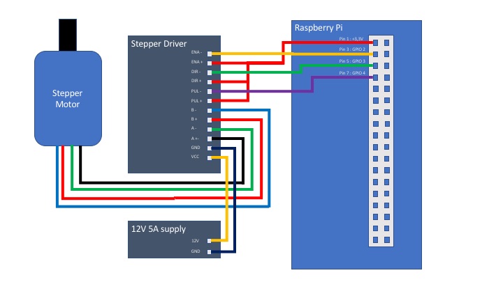
Unless you are brave, I wouldn't go ahead with simply connecting the Raspberry Pi to the stepper driver until you've done some basic tests of your wiring first. I would recommend connecting the GPIO cables to the stepper driver, but performing the following tests with the connector removed from the driver first to see if the signal levels coming out of the Raspberry Pi are correct and hence connected correctly.
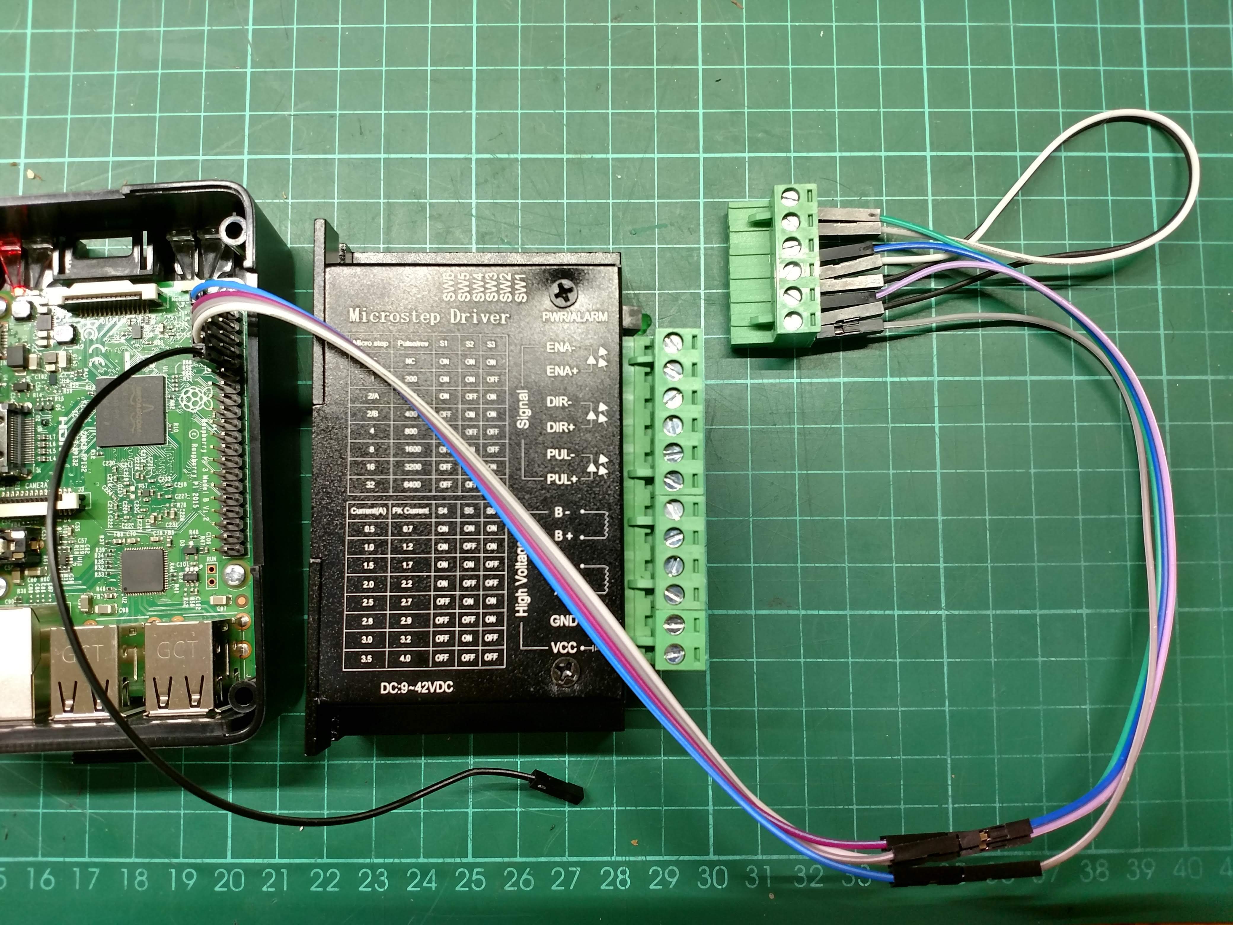
From the top of the connector you have access to the following pins:
- ENA-
- ENA+
- DIR-
- DIR+
- PUL-
- PUL+
Also in the picture you will see a black cable connected to GPIO pin 9 which is a 0V point.
Run the all_low script as follows:
python3 all-low.py
The console should have shown this:
setting all pins low: ENA-, DIR- and PUL-
pi@raspberrypi:~/wheel-cutter $
At this point you should use a multimeter to test the voltages of each pin using the GPIO pin 9 as a 0V reference. You should get the following:
| Pi | Voltage |
|---|---|
| ENA- | 0V |
| ENA+ | 3V |
| DIR- | 0V |
| DIR+ | 3V |
| PUL- | 0V |
| PUL+ | 3V |